EFFECTS OF TRANSPARENT PROTECTIVE COVERS ON LIGHT DISTRIBUTION
RELATED CONTENT:

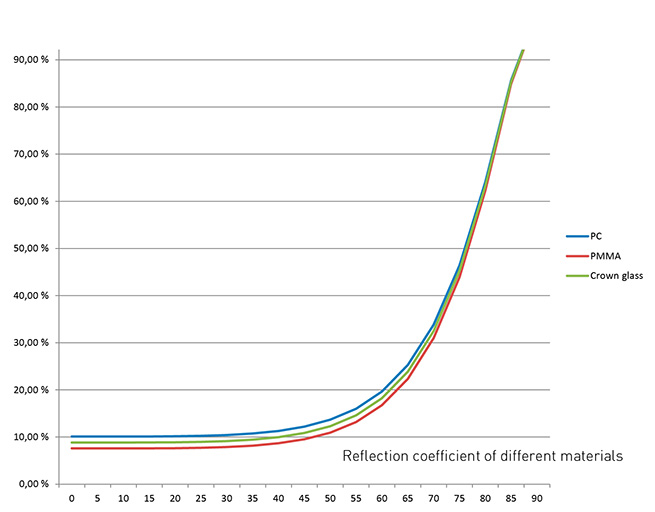
Using transparent protective covers in luminaires affects light output. Internal reflections in the transparent cover can substantially reduce light output, especially in wider angles. The side-effects of internal reflection can be minimized with proper optical design.
Main properties affecting reflection coefficient and therefore efficacy of the luminaire are:
- Inside colour of the luminaire
- Reflection coefficient of the transparent cover
- Beam width
This effect can also be used to shape light, for example to reduce glare in street lights. Because most of the blocked light is actually reflected back inside the luminaire, it can be recycled to improve luminaire efficacy.
In order to minimize reflection coefficient in the luminaire, transparent covers should be made from material with a low refractive index. The amount of light absorbed by the cover is less than 1% so internal reflections are a determinating factor in reducing efficacy. The thickness of the cover doesn’t have a substantial effect on the light.
EFFECTS OF DIFFERENT PROTECTIVE COVER TYPES ON STRADA-ME

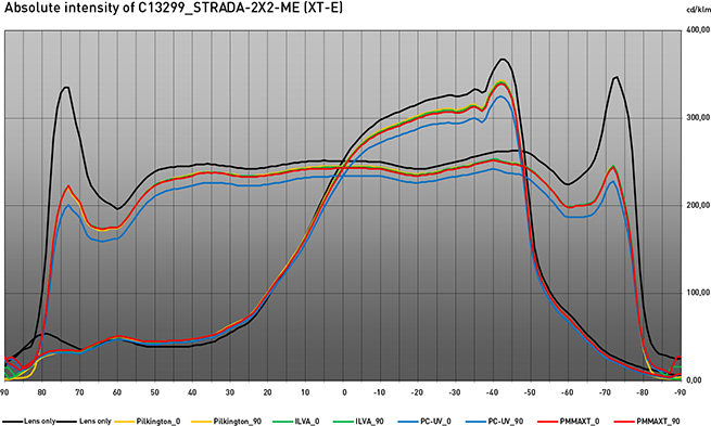
In the above diagram can be seen the effect that transparent protecting cover has on the light output. Optic used in the comparison is LEDiL’s STRADA-2X2-ME module. Module is optimised for European ME road lighting class. The effect of the cover is noticeable in the extremities of beam angles, especially in horizontal plane at gamma angles of around 75°.
This effect can be used in advantage to reduce glare and achieve acceptable TI figures. Light that is reflected from the cover back inside the luminaire can be recycled to add up overall illumination levels so there is only neglible impact on the overall efficiency.
Testing was done with polycarbonate and PMMA cover plates and two different toughened cover glasses from Pilkington and ILVA. Thickness of each cover was 4 mm and covers were mounted 20 mm from the PCB. Test fixture had non-reflective inner surface and light output of the setup was measured with the optogoniometer in 5 degree intervals.
The information contained herein is the property of LEDiL Oy, Joensuunkatu 7, FI-24100 SALO, Finland and is subject to change without notice. Please visit www.ledil.com for additional information, such as the latest photometric files, 3D mechanical models, and application notes relating to handling, gluing and taping.

